A
pipeline traverses through various diverse locations which are difficult to approach during regular operation. For the construction of the
pipeline enormous chunk of land is temporarily acquired by the Pipeline Operator from the land owners. Once the
pipeline is buried, land is returned to the owners for their use such as agriculture etc. which limits the accessibility to the
pipeline in due course of time. Therefore,
pipelines are required to be constructed such that it requires minimal human interference during operation and ensures high level of safety & integrity throughout its design life. The onus to fulfill such high quality and reliability standard rests on the first building block of any
pipeline i.e. line pipes.
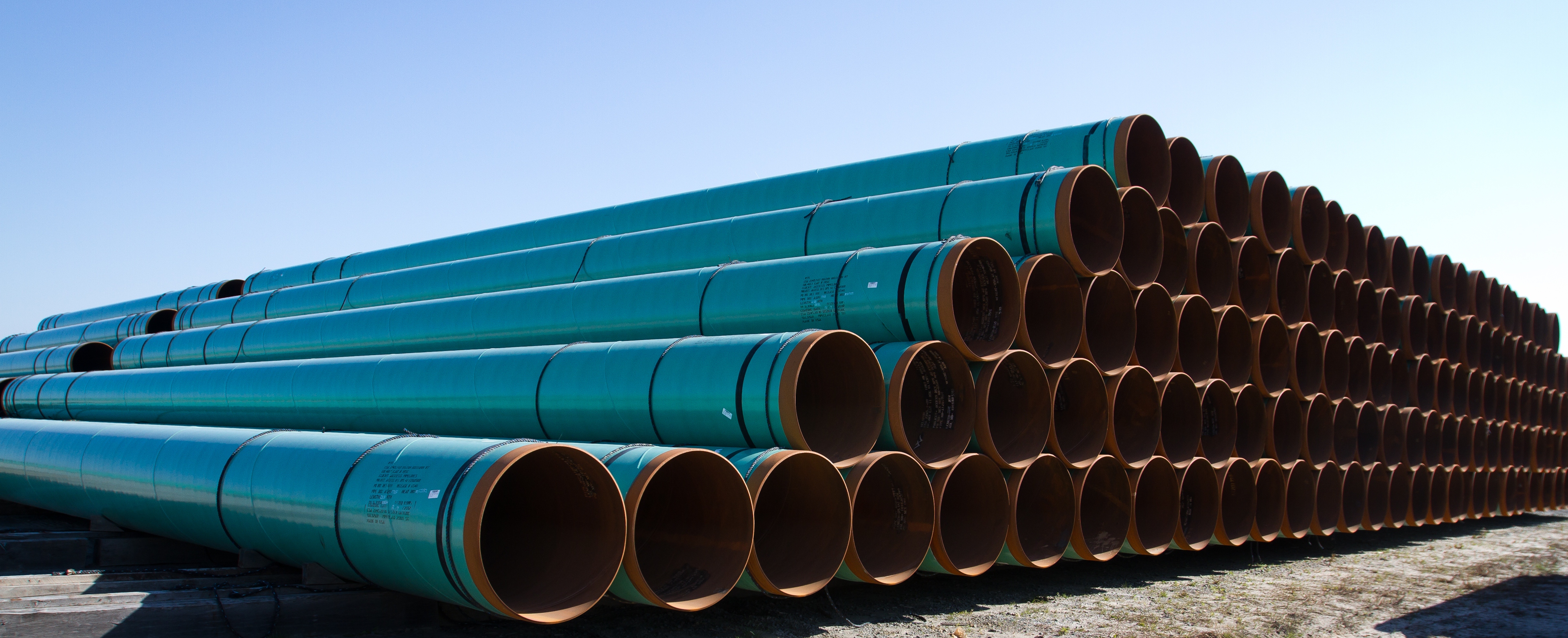
Line pipes are defined as welded or seamless pipes, available with the ends plain, beveled, grooved, cold expanded, flanged, or threaded; used for the construction of
pipelines principally used to convey gas, oil or water (ref 1). The
pipeline fraternity often faces a question that
what is so special about line pipes? Why piping pipes (pipes used for station piping such as ASTM A106) can’t be used for the construction of
pipelines? So this article is focused on the essentials of line pipes for resisting the design loads which a
pipeline system has to accomplish for safe operations.
- Line pipes govern the project quality, fabrication/ installation schedule and most importantly project CAPEX.
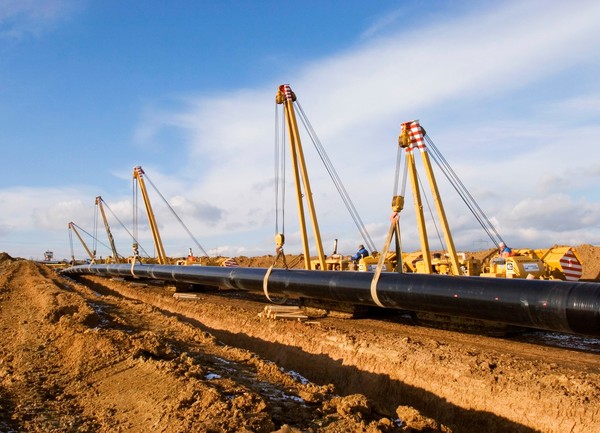
- Line pipes shall be capable to resist weathering during storage, transportation (through places where no motor-able roads are available) and during service.
- Line pipe shall be capable of being laid i.e. it shall be capable to bear installation stresses without any plastic deformations or deformations within the tolerance range.
- Pipeline girth welding is performed on field, which implies, welding under uncontrolled and extreme conditions. So line pipes metallurgical properties, end tolerances etc. shall be capable of tolerating the limitations of field welding by a Laying Contractor. Also, the mechanical and chemical properties shall be such that the girth weld retains its reliability in as-built condition throughout the design life of the pipeline.
- Line pipes shall also have inherently high crack propagation resistance or resistance to ductile fracture propagation to control damage in case any crack is initiated in high strength line pipes.
In a pipeline system, apparently it appears that line pipes procurement constitutes 30-45% (may vary depending upon project) of the project cost, but all other spending (except RoU acquisition cost) such as transportation & logistics, installation schedule, installation cost and overall quality & reliability of the pipeline system is indirectly dependent upon the selection of line pipe.
Based on the fabrication processes, generally following types of line pipes are being used in hydrocarbon pipeline system.
| Process of manufacture |
Size
inches (mm) |
Yield Strength
psi (MPa) |
| Seamless |
(SMLS) |
4.5 (114.3) to 16 (406.4) |
35500 (245) to 70300 (485) |
| High Frequency Welded |
(HFW) |
4.5 (114.3) to 20 (508.0) |
35500 (245) to 70300 (485) |
| Submerged Arc Longitudinal Welded |
(SAWL) |
16 (406.4) to 56 (1422) |
35500 (245) to 80500 (555) |
| Submerged Arc Helical Welded |
(SAWH) |
18 (457.0) to 56 (1422) |
35500 (245) to 80500 (555) |
Note: The above table is informative only and is based on widely used practices. Size range and yield strength range may vary.
API Spec 5L
Specification for Line Pipe
DNVGL-ST-F101
Offshore Pipeline Systems
ISO 3183
Petroleum and natural gas industries - Steel pipe for pipeline transportation systems
CSA Z245.1
Canadian Standard – Line Pipes
GOST 10704
Russian Standard - Steel Pipe
Although there are various international line pipe specifications, conventionally every Company procures line pipes as per their own specifications. These company specs are generally modification of international specifications mostly API Spec 5L.
Chemical composition has a profound effect on the microstructure, mechanical properties, weldability and corrosion resistance of modern line pipe steels. Predominant material for line pipes is C-Mn Steel or Carbon steel. The material for modern line pipes is high strength low alloy (HSLA) steel. The evolution of this special class of steels can be traced back to 1959 when the first X-52 micro-alloyed, or so called high strength low alloy (HSLA) steel was installed in North America. Prior to that line pipe was produced from steels strengthened by carbon and manganese which exhibited very poor weldability and fracture resistance. Strengthening by micro-alloying with niobium and vanadium, in amounts often much less than 0.10 percent, allowed the required strengths to be achieved at lower carbon contents which improved both weldability and notch toughness.
Killed Steel: Steel used for manufacture of pipe shall be fully killed and fine grained. Killed steel means fully de-oxidized steel. Liquid steels contain dissolved oxygen after their conversion from molten iron, but the solubility of oxygen in steel decreases with temperature. As steel cools, excess oxygen can cause blowholes or precipitate as FeO. These blow holes also results in formation of laminations during steel rolling process. Thus, steel shall be killed/ de-oxidized by using Silicon (Si) and/ or Aluminum (Al) or Titanium (Ti) etc.
Fine grained: Fine grained structure of steel increases the strength of the pipe i.e. closer the grain structure, more is the strain resistance. Therefore steel used for line pipe fabrication are fine grained with ASTM grain size number 7 or finer as per ASTM E 112.
Concast Steel:Steel shall be made by continuous casting only to achieve improved yield, quality, productivity and cost efficiency.
Carbon (C)
The microstructure of line pipe steels in grades up to at least X-65 (446 MPa) consists of ferrite and pearlite. Carbon increases the volume fraction of pearlite and thereby strength, however, during welding, the carbon dissolves in the matrix and produces hard brittle microstructures in the region adjacent to the weld bead (the so called heat affected zone or HAZ)). The HAZ may crack immediately, or after some time (delayed cracking) depending on hardness and on the amount of hydrogen introduced by the welding consumable(s).
Manganese (Mn)
It is always advantageous to keep Mn in the vicinity of 1.4% in order to control the hardenability of the base line pipe material. Again Mn should always be considered along with other materials for overall effect, 1.4% Mn max., has been found to be ensuring adequate strength and toughness whole limiting to the hardenablity to acceptale level, without effecting any other properties of the line pipe.
High Mn leads to centerline segregation?
Manganese combines with sulfur (S) which eliminates hot shortness (low ductility due to the formation of iron sulfides at high temperature) but the benefit comes at a price. Manganese sulfide (MnS) is very plastic at rolling temperatures, compared with the hot steel itself, and it elongates to produce inclusion stringers which introduce directionality (anisotropy) into the skelp, such that testing transverse to the rolling direction (generally circumferential direction) results in much reduced, generally unacceptable, ductility and notch toughness (low Charpy energy values).
Silicon (Si)
In a similar way to manganese (Mn), chromium (Cr), nickel (Ni), copper (Cu), and molybdenum (Mo), silicon (Si) provide modest strength increases through solid solution hardening. However silicon is a ferrite stabilizer which tends to raise the γ → α transformation temperature, and stimulate the formation of proeutectoid ferrite which works counter to the beneficial effects of the other solid solution hardening elements in facilitating ferrite grain refinement.
Silicon's principal role is as a deoxidizer. When used in combination with aluminum it eliminates the oxygen introduced into the steel during the steelmaking and refining process thereby preventing carbon monoxide formation and resulting porosity during solidification.
Copper (Cu)
Cu is one element which is considered desirable in the steel as it imparts better atmospheric corrosion resistance during the period between its production and installation. In case of sour service P/L, it is known to improve the corrosion resistance properties in certain ranges. However, excessive Cu is known to promote hot shortness leading to fine crack development along the grain boundaries during processing of the steel or during welding. Therefore, taking into account the possibility of segregation also, Cu is limited to 0.35%, when it is intentionally added. For critical sour service application the range recommended is 0.2 to 0.35% & for non-sour services 0.35% (max.), without insisting on the minimum.
Chromium (Cr)
Cr is an element which increases hardness and carbon equivalent (CE) without substantially increasing the corrosion resistance when present in small quantities. In order to control the hardness of heat affected zone and weld in the as welded condition, such as in case of pipeline, limiting the Cr to 0.2% max. is an appropriate and desirable step that ensures desirable properties in the weld metal. Increasing the Cr content will also affect yield to tensile ratio which needs to be controlled during pipelaying.
Chemistry control is required to improve surface quality & corrosion resistance, and ensure consistent micro-structure, mechanical properties and adequate separation between yield strength and tensile strength.
Wall thickness
The primary description of any pipe always includes wall thickness of the pipe along with diameter and material grade. Tonnage of the line pipes is directly proportional to the square of wall thickness. Selection of wall thickness is dependent upon the internal and external loads which it has to sustain throughout its design life. Internal loads include hoop’s stress due to internal pressure of the pipeline and external load includes:
- Dead loads such earth load (if pipeline is buried), external water pressure (if pipeline is in offshore or water body).
- Cyclic load such as truck wheel loading, railway loading (if pipeline is laid across highways, rail lines), and wave & current loading (in offshore etc.).
- Axial/ longitudinal loading such as expansion loads (due to temperature difference), residual laying stresses etc.
- Transportation and storage stresses etc.
Various international design codes such as ASME B31 codes, DNVGL-ST-F101, API RP 1111, ISO 13623 etc. and local regulations are available which specifies the requirements for wall thickness selection.
It is the onus of the pipeline designer to specify the pipe wall thickness such that negative fabrication tolerance is also included or considered in the specified thickness.
Note: If you are calculating as per ASME B31 codes and selecting the line pipe spec as per ASME B31 such as API Spec 5L, then there is no requirement for including the negative fabrication tolerance in the specified wall thicknesses as ASME B31 codes includes the same.
Out-of-roundness
Out-of-roundness is generally defined as the difference between the maximum (or minimum diameter) and the nominal diameter, expressed as a percentage of the nominal diameter (ref 3). In DNVGL-ST-F101 and ISO 3162, out-of-roundness is defined as the difference between the maximum and minimum diameters, expressed as a percentage of the nominal diameter. Out-of-roundness of pipe affects two most important aspects of line pipe i.e.:
- Resistance to collapse:
Capability of pipe to resist circumferential external loads is inversely proportional to out-of-roundness i.e. more round the pipe is, more will be its capability to resist collapse under external pressure. For offshore application of pipes, external hydrostatic pressure may become governing and poor out-of-roundness of pipe may lead to selection of higher wall thickness line pipes. Therefore, out-of-roundness tolerance of pipes to be utilized for offshore application shall be kept minimal in order to optimize on wall thickness.
- Girth Welding:
Pipes are required to be welded at their ends circumferentially for the construction of pipeline called girth welding. For high quality girth weld, it is desirable to have a properly aligned pipe ends and high-low to be kept at minimum. Control on misalignment becomes critical with the increase in diameter of the line pipes. Misalignment during welding of large diameter line pipe may cause in-service leaks and ruptures at pressures well below 72 percent specified minimum yield strength (SMYS) (ref 4).
Length
Decrease in number of girth welds during project execution is not only beneficial in reducing the construction time but also reduces the risk of loss of integrity due to failure/ leakage of girth weld during operation. Decrease in the number of girth welds can be achieved by utilization of longer pipes. However, length of pipe is restricted for the ease of line pipe handling during production in the mill as well as transportation & handling during execution at site.
Drawing the balance between the two an average length of pipe as 12.0 m (along with some tolerance in the quantity and variation length) is a common practice in pipeline projects.
- DNVGL-ST-F101, 2017: Submarine Pipelines Systems
- ITI Institute : Technical Report - A Guide for Understanding & Specifying Chemical Composition of High Strength Line pipe Steels
- API Spec 5L: Specification for Line Pipe
- Pipeline Safety: Girth Weld Quality Issues Due to Improper Transitioning, Misalignment, and Welding Practices of Large Diameter Line Pipe: Pipeline and Hazardous Materials Safety Administration (PHMSA)